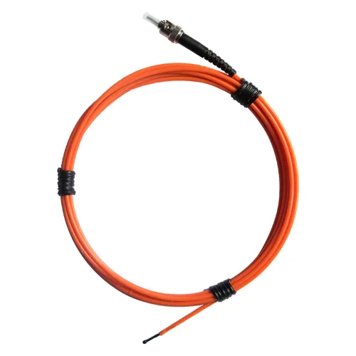
Fluorescent Fiber Optic Temperature Sensor
An electrically passive optical sensing element for direct contact measurement where metallic sensor leads can compromise insulation or signal integrity.

Direct optical measurement at the thermal point
Fluorescence-lifetime probes, multi-channel instruments and application engineering for transformer windings, reactors, switchgear and high-voltage EMI/RFI environments.
Core products
Select the probe for the thermal interface, the instrument for channel and integration needs, and the installation architecture for the equipment insulation system.
An electrically passive optical sensing element for direct contact measurement where metallic sensor leads can compromise insulation or signal integrity.
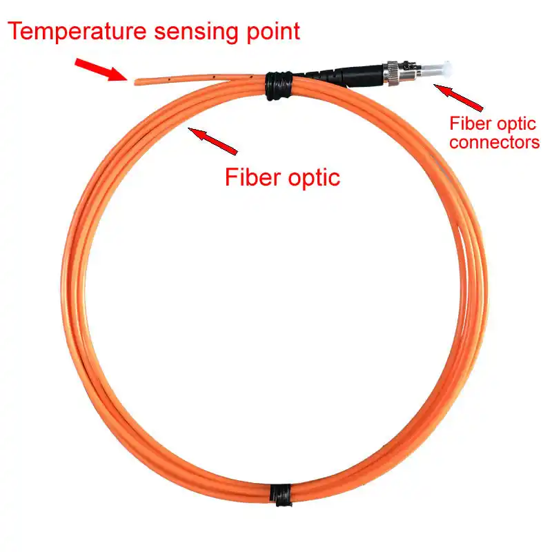
A quartz-fiber probe that carries light to and from a fluorescent sensing tip for point-based temperature measurement.
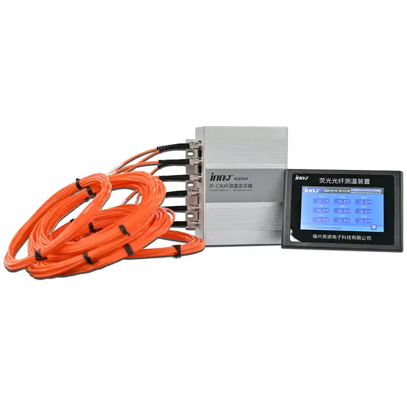
A complete instrument-and-probe platform for collecting point temperatures in electrically demanding environments.
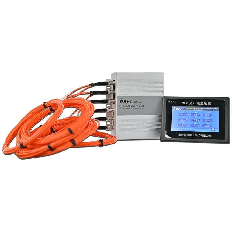
A centralized monitor for organizing multiple fluorescent optical probes into one temperature, alarm and communications layer.
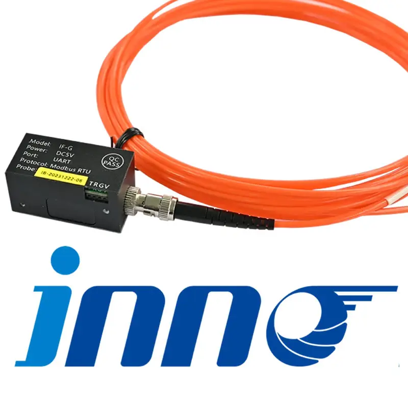
A compact OEM measurement module for equipment manufacturers building fluorescent fiber optic temperature channels into a larger control platform.
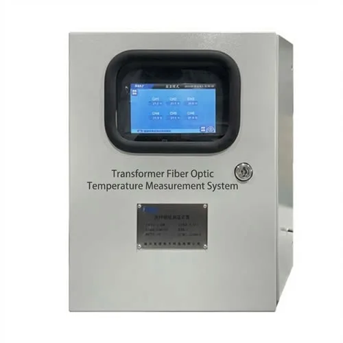
A probe-and-monitor architecture for direct winding temperature measurement during transformer operation.
Fluorescence lifetime
Excitation light reaches a fluorescent sensing tip through quartz fiber. The monitor analyzes the temperature-dependent emission lifetime, keeping the sensing point passive and immune to EMI/RFI.
Power equipment
A transformer fiber optic temperature monitoring system connects fluorescent probes at selected winding points to an external instrument. It reports local temperatures directly, complementing bulk measurements and thermal models. The measurement-point plan, probe construction and monitor interface must match the transformer design.
Winding hot spots are localized thermal conditions shaped by conductor losses, cooling flow and construction. Embedded optical probes complement calculated thermal models with direct measurements at selected design locations.
Oil and top-oil indicators do not directly measure every winding location. Fluorescent probes can be integrated at engineered winding points and routed through a suitable exit arrangement to an external monitor.
Dry-type transformer temperature monitoring uses selected winding measurements to track local thermal conditions. For cast-resin and air-cooled designs, fluorescent fiber optic probes offer an electrically passive measurement point connected to an external monitor. Probe locations and installation must be agreed with the transformer manufacturer before assembly.
Reactor losses and magnetic fields create a demanding measurement environment. Fluorescent fiber optic probes provide a dielectric path to representative internal winding points.
Bolted joints and contacts can develop localized temperature rise as resistance increases. Permanently installed optical probes support continuous trend and alarm data without depending on radio transmission inside a metal enclosure.
Transformer winding hot spots
Probe placement, fixation, optical routing, fiber exit and channel identification should be part of transformer thermal and insulation design—not an afterthought during commissioning.
View winding approach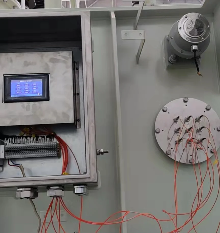
Product selection
Define the physical point, its thermal purpose and the installation stage.
State expected temperature, dielectric environment, routing and mechanical constraints.
Define channels, alarm ownership, display and plant communication requirements.
Technical resources
Understand what a fiber optic temperature sensor measures, the parts of a fluorescent point-sensing system, suitable applications and selection limits.
Follow fluorescence-lifetime temperature sensing from excitation light to decay measurement and calibration, with practical limits for optical signal quality.
A practical engineering guide to fluorescence lifetime temperature measurement explained for high-voltage and industrial equipment.
A practical engineering guide to fiber optic temperature sensor accuracy for high-voltage and industrial equipment.
A practical engineering guide to fiber optic temperature sensor response time for high-voltage and industrial equipment.
A practical engineering guide to fiber optic temperature sensor temperature range for high-voltage and industrial equipment.
Technical questions
It is a point sensor that sends light to a fluorescent tip and calculates temperature from the decay lifetime of the returned emission.
The probe is passive and dielectric at the measurement point, supporting direct winding measurements without conductive sensor wiring in the high-voltage region.
No. The final specification depends on the selected instrument. Confirm channel count and interfaces on the product datasheet.